
 EN
EN



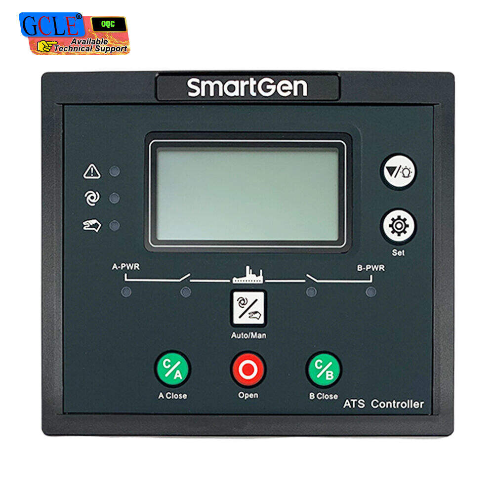
A data center operations manager received an alert at 3:14 a.m. The primary utility feed had dropped, and the facility's single automatic transfer switch was supposed to engage the standby generator within six seconds. Six seconds passed. Then ten. The ATS had suffered an internal contactor failure — a fault that had passed every quarterly inspection — and the entire server farm was running on UPS battery reserves with an estimated 12 minutes of runtime remaining. The engineering team scrambled to manually bypass the failed switch while the facility's SLA clock ticked toward a seven-figure outage penalty. After that night, the question was no longer theoretical: can an ats switch be installed in parallel with another unit so that no single device failure can isolate critical loads from backup power?
The short answer is yes — parallel ATS configurations are not only technically feasible, they represent the industry-standard approach for facilities where downtime tolerance is measured in seconds, not minutes. Hospitals, data centers, pharmaceutical manufacturing lines, and telecom switching centers routinely deploy multiple transfer switches in parallel arrangements to create N+1 redundancy at the transfer level. What makes a parallel transfer switch deployment succeed or fail depends on far more than bolting two units onto the same busbar. Coordination logic, source synchronization, and maintenance access design determine whether the redundancy on paper translates into actual uptime during a real-world failure.
Understanding Parallel ATS Switch Configurations
What Does "Parallel ATS Installation" Actually Mean?
Parallel ats switch installation refers to an arrangement where two or more automatic transfer switches operate from the same set of power sources — typically a utility feed and one or more standby generators — with each ATS serving a separate load bank while maintaining the ability to cross-connect if one switch fails. The term "parallel" describes the electrical topology: the switches sit in parallel relative to the source bus, not in series. A series arrangement would route power through ATS-1 to ATS-2, meaning a failure of the first switch kills power to everything downstream. A parallel arrangement gives each transfer switch independent access to both the normal and emergency power sources.
This configuration differs fundamentally from a cascaded or daisy-chained setup. In true parallel topology, the failure of any single transfer switch does not prevent the remaining operational units from transferring their assigned loads to backup power. The design intent is fault isolation — containing a switch-level failure within the boundaries of its protected load segment rather than letting that failure propagate across the entire backup power system.
Where Parallel ATS Setups Are Commonly Deployed
Facilities that adopt parallel transfer switch architectures share a common operational profile: the financial and safety consequences of power interruption far exceed the incremental cost of adding redundant switching equipment. A medium-sized hospital typically runs three to five parallel ATS units — one for life-safety circuits, one for critical care equipment, and additional units for HVAC and general building loads. Each operates independently, but all draw from the same generator plant. If the life-safety ATS fails to transfer, the critical care ATS remains fully functional because it maintains its own direct connection to the emergency bus.
Data centers deploy parallel transfer switches differently but with the same fundamental logic. A Tier III or Tier IV facility runs dual power paths from separate ATS units to each server rack, often combining static transfer switches for sub-cycle switching with mechanical ATS units for sustained backup operation. Telecom central offices, continuous-process chemical plants, and airport control towers round out the list of applications where parallel ATS deployment counts as standard engineering practice rather than optional redundancy.
The Core Benefit: Eliminating Single Points of Failure
A single ats switch serving an entire facility creates one of the most concentrated single points of failure in any power distribution system. The switch mechanism itself — whether contactor-based, motorized breaker, or solid-state — contains mechanical components subject to wear, electronic control boards vulnerable to transient voltage damage, and sensing circuits that can drift out of calibration. When that single unit fails, every circuit downstream loses access to backup power regardless of how many generators sit on standby.
Parallel configuration distributes this risk across multiple independent switching paths. Each transfer switch carries its own control logic, its own voltage sensing inputs, and its own transfer actuator. A firmware fault in one controller does not propagate to the others. A welded contactor on unit two does not prevent unit three from picking up its assigned load bank. The facility achieves transfer-system redundancy without duplicating the entire generator plant — a cost structure that makes parallel ATS the pragmatic choice for any operation where uptime directly impacts revenue or safety.
Technical Mechanics Behind Parallel ATS Operation
How Two ATS Switches Coordinate Transfer Sequences
When utility power fails, every parallel transfer switch in the facility detects the voltage sag or loss independently through its own sensing inputs. Each unit initiates its generator start signal, but typically only one ATS is designated as the master start controller — a role assignment configured through programmable logic or hardwired interlock wiring. The master unit sends the start command to the generator set; the slave units wait for stable generator voltage before executing their own transfer sequences.
This coordination prevents a scenario where multiple ATS units simultaneously attempt to transfer to generator power before the generator has reached stable voltage and frequency. The generator controller needs a defined window — typically 8 to 15 seconds depending on engine size and governor response — to ramp to rated speed and build stable output. If every parallel transfer switch started pulling load during generator ramp-up, voltage sag under combined inrush current could trip the generator's undervoltage protection and send the system into an unrecoverable lockout state.
The coordination sequence follows a predictable pattern. Master ATS detects source failure → sends start signal → generator reaches 90% rated voltage and frequency → master ATS transfers → slave ATS units transfer in staggered sequence, typically 2–4 seconds apart, to avoid simultaneous inrush from all load banks hitting the generator simultaneously. This staggered transfer timing is programmable on modern microprocessor-controlled units and configurable through DIP switches or rotary dials on electromechanical models.
Load Isolation and Source Synchronization Requirements
A fundamental safety requirement for parallel ATS operation involves preventing back-feed from the generator into utility lines — a condition that creates electrocution hazards for utility line workers and violates interconnection standards. Each transfer switch must maintain physical isolation between the normal source and the emergency source at all times. The mechanism that enforces this is the mechanical interlock: a physical barrier or linkage that makes it mechanically impossible for both source connections to close simultaneously within a single switch housing.
UL 1008, the North American standard governing transfer switch equipment, mandates specific mechanical interlock designs and dielectric withstand testing to verify isolation integrity. The standard requires that the interlock withstand 10,000 operations without failure — a design-life benchmark that directly impacts component selection and actuator sizing. When specifying parallel transfer switch configurations, verifying UL 1008 listing on every unit provides baseline assurance that the interlock mechanism meets these requirements.
Source synchronization becomes critical when deploying closed-transition transfer switches in parallel. Closed-transition ATS units momentarily parallel the utility and generator sources during transfer — typically for less than 100 milliseconds — to achieve seamless load transfer without the brief power interruption characteristic of open-transition switching. For parallel closed-transition operation, the generator's voltage, frequency, and phase angle must match the utility within tight tolerances, usually ±5% voltage, ±0.2 Hz frequency, and ±5 degrees phase angle. A synchronizing relay or controller monitors these parameters and blocks transfer if they fall outside acceptable limits. Parallel ATS installations using closed-transition switching demand synchronization-grade generator controllers — standard voltage-sensing modules lack the precision required for repeated safe paralleling.
Communication Protocols That Prevent Cross-Connection
Modern parallel transfer switch installations rely on structured communication between units to prevent operational conflicts. Two primary architectures dominate the market: hardwired interlock signaling using dry-contact relays, and network-based communication using Modbus RTU, CAN bus, or proprietary protocols running over RS-485 or Ethernet physical layers.
Hardwired interlocking uses dedicated conductors between ATS controllers to transmit permissive signals. ATS-1 sends a "generator available" confirmation to ATS-2 before ATS-2 initiates its transfer sequence. ATS-2 sends a "transfer complete" acknowledgment back to ATS-1. This closed-loop handshake ensures both units operate from the same system-state understanding — preventing the situation where one switch transfers to generator power while the other remains locked on utility, creating a cross-connection hazard through shared neutral or ground paths.
Networked communication adds diagnostic visibility. A master controller — often integrated into the generator set controller or a standalone system-level PLC — polls each parallel transfer switch for status data: source voltages, switch position, load current, fault codes, and maintenance counters. This aggregated data feeds into building management systems and remote monitoring platforms, giving facility managers real-time visibility into the health of every transfer switch in the parallel array. From a procurement standpoint, specifying ATS units with open-protocol communication ports avoids vendor lock-in and allows integration with existing facility monitoring infrastructure.
Real-World Applications and Risk Considerations
A Hospital Power System That Could Not Afford a Single ATS Failure
A 280-bed regional hospital in Southeast Asia operated for twelve years with a single 1,600-amp automatic transfer switch serving the entire facility. The hospital's engineering team maintained the unit diligently — contact resistance tests every six months, infrared thermography annually, transfer testing under load quarterly. The ATS performed flawlessly through 47 recorded utility outage events over that twelve-year span.
In year thirteen, a phase-to-phase fault developed inside the ATS enclosure during a routine utility switching operation by the local power authority. The fault vaporized a section of busbar before the upstream circuit breaker cleared, but not before the switch housing sustained structural damage that made the entire unit inoperable. The standby generators started and reached rated voltage, but the failed ats switch could not complete the transfer. Critical care circuits lost power for 23 minutes while electricians manually disconnected the damaged switch and back-fed the emergency distribution panel through temporary cabling. No patient harm occurred, but the hospital's accreditation body issued a formal finding requiring transfer-system redundancy before the next review cycle.
The hospital's retrofit installed three parallel ATS units — one dedicated to life-safety circuits, one to critical care equipment, and one to general building services. Each transfer switch maintained an independent control system, independent sensing inputs, and independent mechanical interlock. The total installed cost ran approximately 40% higher than replacing the single unit with an equivalent single switch, but the fault-containment benefit meant that any future single-switch failure would affect at most one-third of the facility's power distribution — and zero critical care or life-safety loads if the failure occurred in the building-services unit.
Common Misconfigurations That Create Hidden Vulnerabilities
Parallel ATS deployments fail to deliver expected redundancy when design oversights introduce shared dependency points that defeat the purpose of parallel topology. One recurring pattern involves common control power supplies. If all parallel ATS controllers draw their DC control power from a single battery charger or AC-DC converter, a failure of that supply disables every transfer switch simultaneously — effectively converting a parallel configuration into a single-point failure regardless of how many physical switch housings are installed.
Another vulnerability arises from shared sensing inputs. Some installations use a single set of voltage transformers on the utility bus to feed sensing signals to multiple ATS controllers. If that transformer set fails or its fusing opens, every controller simultaneously loses utility voltage reference and may initiate unnecessary transfers or lock out. Proper parallel design requires independent sensing paths for each transfer switch — either dedicated voltage transformers per unit or redundant transformer sets with isolated secondary windings feeding separate sensing circuits.
Common neutral and ground connections represent a third design consideration. When multiple transfer switches share a common neutral bus without individual switching of the neutral conductor on each unit, ground-fault current paths can bypass the overcurrent protection coordination scheme. The NEC and IEC 60364 address this through requirements for 4-pole switching in specific parallel ATS configurations — where the fourth pole switches the neutral conductor — to prevent objectionable current flow through parallel neutral paths.
Procurement and Installation Guidance
Key Specifications to Verify Before Specifying Parallel ATS
Selecting the right ats switch for parallel deployment starts with verifying fundamentals that directly determine operational reliability. The withstand and closing rating, measured in RMS symmetrical amperes, indicates the fault current the switch can safely close into and carry for a specified duration without contact welding or structural damage. A parallel configuration where each ATS carries a portion of total facility load can use units with lower individual WCR values than a single-switch design — but each unit must still be rated for the available fault current at its connection point, which depends on transformer impedance and upstream protective device characteristics.
Transfer timing specifications matter differently in parallel configurations than in single-switch designs. An ATS serving life-safety loads must transfer within 10 seconds per NFPA 110 requirements. The staggered transfer sequencing used in parallel installations adds cumulative delay — if the master unit transfers at T+10 seconds and two slave units stagger at 3-second intervals, the last load bank transfers at T+16 seconds. Verifying that this cumulative delay falls within acceptable limits for the served loads prevents operational issues during commissioning.
Control voltage requirements deserve particular attention. Some ATS controllers operate on 24 VDC derived from the generator starting battery; others use 120 VAC control power from the utility side. In a parallel configuration, standardizing on a single control voltage simplifies wiring and reduces the parts count for spare controller modules. Battery-backed control power ensures the ats switch can complete a transfer even when both utility and generator power are unavailable — a capability that matters most during black-start scenarios where the transfer sequence must execute on battery power alone.
Maintenance Practices That Preserve Parallel Redundancy
Parallel ATS redundancy exists only as long as every unit in the array remains functional. A parallel configuration with one failed ats switch is no longer parallel — it simply shifts the single point of failure to whichever unit remains operational. Maintenance programs for parallel installations must treat each switch as an independent asset with its own inspection schedule and its own replacement parts inventory.
Annual transfer testing under load verifies that each transfer switch can carry its rated load current through the complete transfer sequence without overheating, without excessive voltage drop, and without nuisance tripping of downstream protective devices. Infrared thermography during load testing identifies loose connections — a leading cause of ATS failure — before they progress to thermal runaway. Contact resistance measurements on main and transfer contacts, compared against baseline values recorded during commissioning, provide early warning of contact wear and pitting.
Bypass isolation mechanisms allow maintenance on one transfer switch without dropping the loads it serves — a critical feature for parallel installations in continuous-operation facilities. A bypass-isolation ATS includes a manual bypass switch that routes power around the automatic transfer mechanism, allowing technicians to isolate, inspect, and service the automatic switch while the load remains powered through the bypass path. Parallel configurations that include bypass-isolation on each unit achieve the highest practical level of maintainability because any single switch can undergo service without affecting facility operations.
Frequently Asked Questions
Can two ATS switches share one generator?
Yes, multiple ATS units can share a single generator as the emergency power source. Each ats switch connects independently to the generator output bus. The generator must be sized to handle the combined load of all connected ATS units, and the start/transfer sequence must stagger the load pickup to avoid overloading the generator during ramp-up. Generator controllers with multi-ATS coordination capability manage this staggered loading through programmable transfer delay timers on each ATS unit.
What is the difference between parallel and cascaded ATS installation?
Parallel installation places ATS units side by side on the same source bus, with each serving independent load banks. Cascaded installation routes power through one ATS into another, creating a series dependency. In a cascaded setup, failure of the upstream transfer switch disables all downstream units. Parallel topology isolates each switch failure to its protected load segment.
Which standard governs ATS switch safety requirements?
UL 1008 covers transfer switch equipment in North America, specifying construction, performance, and testing requirements including withstand and closing ratings, temperature rise limits, and endurance testing. IEC 60947-6-1 addresses transfer switching equipment under the international standards framework. NFPA 110 provides additional requirements for emergency and standby power systems, including transfer switch placement and operation for life-safety applications.
How much spacing is required between parallel ATS units?
Physical spacing depends on local electrical code working-clearance requirements, typically 36 inches (914 mm) of front clearance for equipment operating at 0–150 volts to ground, increasing to 42 inches for 151–600 volts as defined in NEC Article 110. Heat dissipation also factors into spacing — each transfer switch generates heat from contact resistance and control transformer losses. Manufacturer specifications for minimum side clearance should be followed to prevent thermal derating from restricted airflow.
Can parallel ATS switches use different manufacturers?
Technically possible, but not recommended without detailed engineering review. Different manufacturers use different communication protocols, different transfer timing characteristics, and different interlock logic implementations. Mixed-vendor transfer switch installations require custom engineering to resolve protocol incompatibilities and verify coordination timing. Single-vendor sourcing simplifies integration testing, spare parts management, and technical support coordination.
What maintenance interval is recommended for parallel ATS installations?
Semi-annual visual inspection and annual load-transfer testing per manufacturer guidelines and NFPA 110 requirements. Facilities with high transfer frequency — such as those in regions with unstable utility grids — benefit from quarterly contact resistance testing. Each transfer switch in a parallel array follows its own maintenance schedule independent of other units.
How does a bypass-isolation ATS work in a parallel configuration?
A bypass-isolation transfer switch includes a manual bypass mechanism that parallels the automatic transfer path. When activated, the bypass carries load current around the automatic switch, allowing the automatic mechanism to be isolated and withdrawn for service. In a parallel configuration, bypass-isolation on each unit enables maintenance without dropping any load bank — service can be performed on one unit while others remain in automatic operation.
Why does staggered transfer timing matter in parallel ATS?
Staggered transfer prevents the generator from experiencing simultaneous inrush current from all connected load banks. If every ats switch transferred to generator power at the same instant, the combined starting current from motors, transformers, and capacitor banks could pull generator voltage below the undervoltage trip threshold, causing the generator to shut down. Staggering transfers by 2–4 seconds per unit allows the generator to stabilize after each load step before the next unit transfers.
Choosing a Reliable Power Transfer Solution Partner
Electrical system designers evaluating parallel ATS configurations need more than specification sheets from a vendor — they need engineering depth from a partner who understands the full power distribution ecosystem. GCLE brings this perspective through fifteen years of specialization in generator control and power transfer technology. The engineering team designs transfer switch solutions for applications spanning 150 countries, from single-unit standby installations to multi-switch parallel architectures serving critical infrastructure.
GCLE's manufacturing operation integrates controller development, switchgear fabrication, and system-level testing under one quality management framework. Each ats switch undergoes factory acceptance testing that verifies transfer timing, interlock integrity, and withstand capability before shipment — reducing the commissioning surprises that delay project schedules in the field. For facilities pursuing parallel redundancy, GCLE offers pre-engineered coordination packages that include programmable transfer sequencing, communication integration, and documentation supporting compliance verification against UL 1008 and regional electrical codes.
The supplier relationship extends beyond delivery. GCLE maintains application engineering support for system design review, commissioning assistance for parallel installations, and technical documentation that includes wiring diagrams, coordination study data, and maintenance planning guides. Power systems that depend on parallel transfer redundancy for uptime depend equally on a supply chain that delivers consistent quality, predictable lead times, and responsive technical support — outcomes that flow from working with a partner whose core business is generator power management rather than treating transfer switches as a secondary product line.

