
 EN
EN



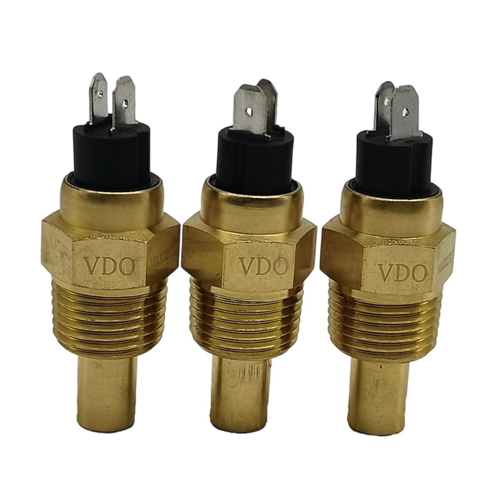
Critical Generator Sensor Types and Their Essential Placement
Engine temperature and oil pressure sensors: an installation near temperature and oil sources
Engine temperature and oil pressure sensors play a role in determining the reliability of a generator. Temperature sensors should be installed directly to coolant flow and/or engine heads to monitor the torch and should be mounted less then 6 inches away from combustion chambers. Avoid direct flame and/or exhaust. Oil pressure sensors must be installed in the lubrication main gallery and extreme high pressure to capture the system pressure true to the main filter. Following NFPA 110, both sensors must be thermally insulated and mounted in a way that prevents vibration when the temperature exceeds 125°F.
Voltage, frequency and current sensing for load: placement to capture relevant electric parameters
In order to avoid a drift in measurement and loss of fidelity in the control system, placement of electrical sensors is critical. Current transformers encircle all three-phase conductors at the generator output. They should be placed directly downstream of the alternator stator windings, and directly upstream of all protection devices. Sensing for voltage should be done directly and downstream of the main output protective device. Frequency sensing should be done at the high end of the alternator tuning windings. Whenever possible, allow for at least twelve inches of clearance to be given to high current cabling, as this may result in a competitive installation signal degradation of up to 2%.
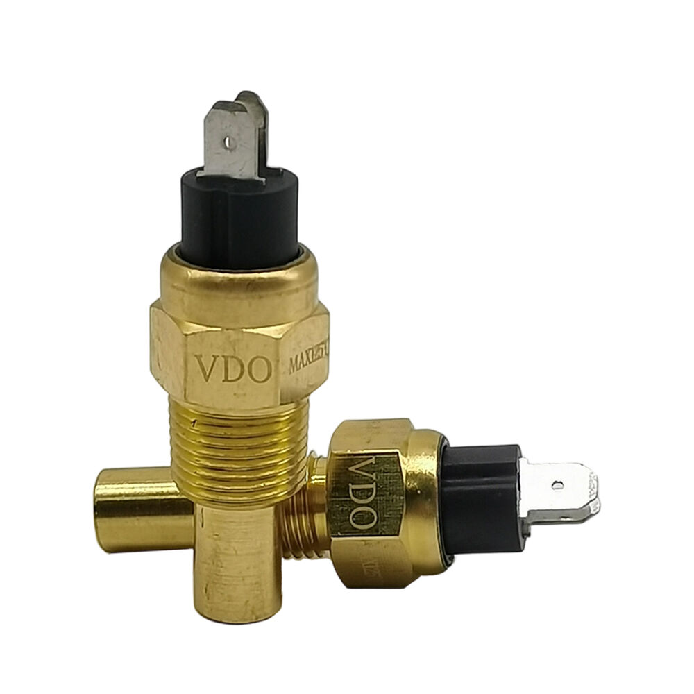
Exhaust gas temperature (EGT) sensors: positioning, precision, and trade-offs between longevity and thermal responsiveness
The trade-off between thermal sensitivity and longevity is apparent with EGT placement. EGT sensors installed directly on the exhaust manifold detect thermal signals fastest, in about 0.5 second, compared to 2-3 seconds when installed downstream. However, they also endure extreme thermal cycling with temperatures raging more than 1800°F (~982°C) about 1,800°F (982°C), calling for Inconel or high temperature alloys, in addition to the 2-3 seconds of thermal lag. It is also possible to build the EGT sensors downstream such that they do not have the lengthy thermal lag, thermal cycling conditions downstream, and spacing of 18-24 inches is optimal spacing (to be placed about 18-24 inches downstream, and in a vertical and 10 or 2 o’clock position, downstream of the exhaust port and before catalytic converters or exhaust stacks).
Regulatory and Environmental Constraints Governing Generator Sensor Placement
Generator sensor placement must be such that they are easily accessible and require only minimal effort to be serviced (NFPA 110 and NEC Article 700). Within the context of weather conditions and the placement of the devices, they must also be labeled in a semi-permanent manner with their function and safety limits. IP-rated (intrusion protection) covers of a minimum of IP54 for controlled environments and IP66 for uncontrolled exposure to the environment must also be ensured to protect the devices from moisture and dust, with a spacing of 18 inches between exhaust manifold (NFPA commissioned thermal imaging) being sufficient thermal conditions that do not cause the system to distort and miscalculate. Sealing in construction environments must not allow particulates 50 microns and greater (OSHA).
How the conditions of physical installation can impose restrictions on sensor placement: obstruction by clearance, ventilation, and enclosure.
Though physical barriers may impose restrictions on placement, optimal technical placement may remain impractical. The installation of a 36-inch service corridor in the vicinity of a generator, always a hot zone and a dangerous vibration zone, may make optimal placement of a sensor remain impractical. Particularly, in the ventilation pathways of most air-cooled units, some optimal placements may need to be sacrificed in the interest of measurement. Cartesian steel support beams, alongside, paradoxically, fuel lines and coolant piping, effectively eliminate many possible places of installation. Electromagnetic interference, as quantified by spacing, reveal that the installation of a current sensor in close proximity to steel support beams results in significant interference. Additionally, when required, placement of a sensor involves great skill and justification to install a sensor, as opposed to a “theoretically” optimal practice, as the placement assures, along with a symmetry of thermal stability and serviceability, signal integrity is achieved.
Compensation of signal integrity and system integration: generator sensor function accountability.
Just as the placement of a sensor requires the justification of signal integrity, replacement of a generator sensor demands justification. As long as the sensor is at risk, a neighboring generator, sensor, or piece of equipment may be required to justify its replacement. A signal may not be received, and if it is, it may not be purged. A signal is defined as a quantity, most commonly dynamic, that, in failure, creates the generator sensor. A measure of dynamic quantity or failure, based on evaluations of the NEMA MG-010-1921 standard, 10 mA, is replaced. In attempting to justify its removal, a failure of a generator sensor may, in effect, be required. To avoid inappropriately justifying generator sensor replacement, structural integrity may require the removal of sp
Robust system integration improves communication across control layers. Fieldbus protocols like Modbus RTU and CAN bus need matched termination impedance to help signal reflections, preventing packet loss and timestamp jitter. For systems integrated with building management systems (BMS), validation testing at full load conditions ensures timestamps are within 10ms of each other. This allows customers to perform effective analysis of cascading faults. An enclosed system architecture and integration of correlation and communication eliminates 73% of false alarms as observed in the NFPA 110 field study. It also provides runtime consistency diagnostics across the various stages of operation such as startup, steady-state and transients.
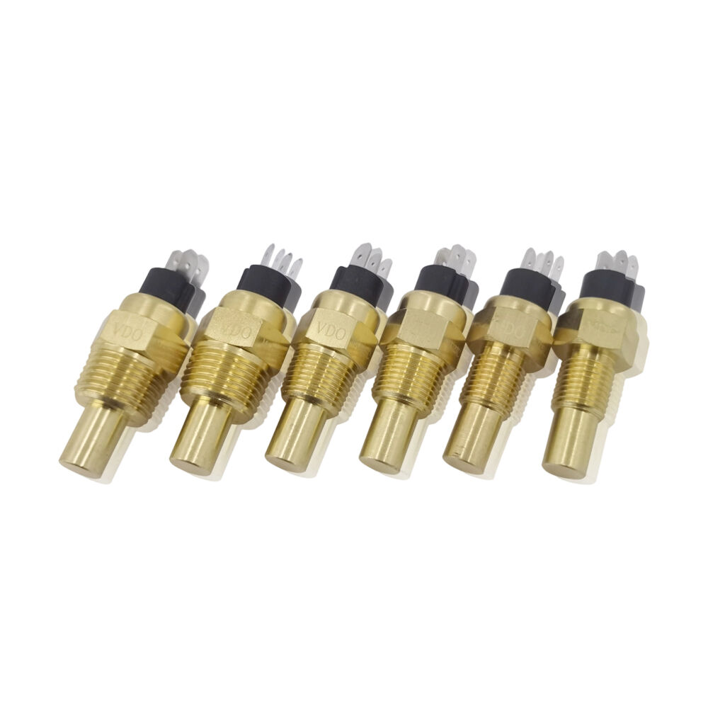
Field-Proven Generator Sensor Placement Patterns Across Application Scales
Generator sensor placement is determined more by operational importance than by system size or application scope. For residential systems of <20 kW, single-point monitoring is most common, with monitoring of temperature, oil pressure, and voltage sensors located. Unshielded signal cables are run to output. For commercial and healthcare systems, the NFPA 99 codes require double redundancy at mission critical interfaces for fault isolation to preserve power to the life safety systems. A redundancy practice is adoption to determine the importance of the fault isolation, and more importantly, to determine the maximum allowable delay of the system.
Frequently Asked Questions
Where should engine temperature sensors be located?
Located as close as possible to a combustion chamber, within 6 inches, for more responsive and accurate measurements. Avoid direct flame or exhaust.
How do you install oil pressure sensors?
To measure the pressure created by the system, the oil pressure sensors must be threaded into the oil system's main lubrication galleries before the oil filter.
Where do voltage and current sensors go?
Voltage sensors fit between the main output breaker and the breaker on the distribution panel, while current transformers go around phase wires at the generator's terminals directly below the alternator.
How do NFPA 110 and NEC Article 700 describe sensor labeling?
With permanent and weather-resistant labels, the function, calibration intervals, and safety limits on the sensors satisfy NFPA and NEC concerns.
How can you be sure that the integrity of your generator sensors' signals is maintained?
Twisted pair cables with continuous shielding grounded, grounded at the control side, and sensor wiring separated from powerful wires will keep the signals of your generator sensors free from disturbance.

